
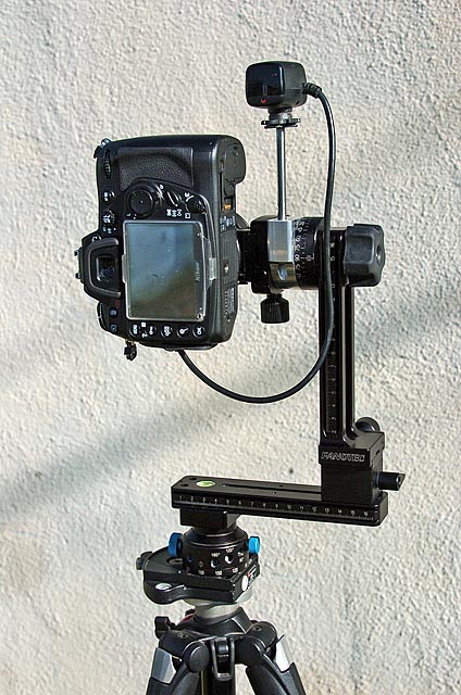
Here are my "tweaks" done to the Nodal Ninja M1L pano head.
None of these are required in order to use the pano head. I just like to play.
|
I am a really big fan of using a lens ring mount instead of an upper arm. I think using an upper arm adds too many parts that do not need to be there. A lens ring mount allows you to swap out camera bodies without doing any major adjustments to the pano head. I sometimes use a battery grip. If I used a camera body plate, I would have to remove it every time I wanted to shoot sports and low light theater. |
| Lets start from the bottom and work our way up as I show you what I have done so far. |
|
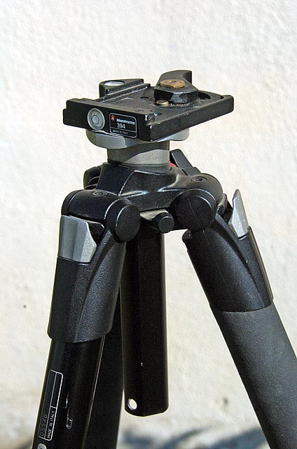
I use a Manfrotto 394 quick release system for attaching the pano head to the tripod. The short center column makes sure the bottom of the center column does not stick out into the picture when taking the Nadir patch shot. |
|
I got tired of using pieces of paper to between the tripod column and the base plate in order to get the base plate oriented correctly with the tripod.. Drilling for two countersink bolts solved the problem. Orienting the pano head to the tripod is the first step in setting up your rig when using the Nadir adapter. |
|
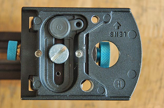
I drilled two holes in the top plate for the anti twist screws that Nick at Fanotech uses in all of his designs. I had to mill away some of the lip on the left edge of the clamp in order to let the rotator sit down flat on the top plate. Since I shoot 6 shots around with my Nikon 10.5 lens, I use smaller and lighter RD4 rotator. If I use a different lens that requires the RD16 that came with the kit, I will have to remove more material from the lips around the plate. |
|
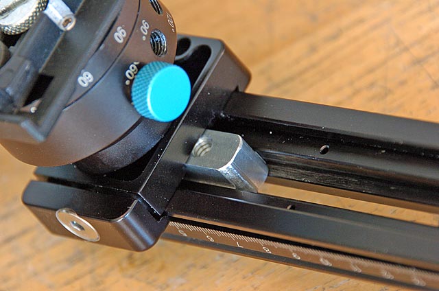
I drilled and tapped for two anti rotation bolts on the bottom of the RD4 rotator. If I ever put the RD16 rotator into service, I would need to drill and tap the same two holes. If you take a very close look you will notice that the locking knob at the right is not in the stock 60 degree position. Repositioning the knob allows for easier access when locking down the rotator before swinging the camera out for the Nadir patch shot.
|
|
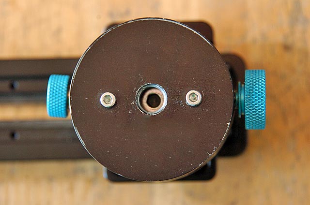
To allow for maximum clearance when the Nadir adapter is swung into position, I removed the locking knob and replaced it with a standard 1/4-20 counter sink bolt. It makes no sense to provide a quick release between the rotator and the lower arm. Set it and forget it. |
|
If I were to implement a quick release clamp on the rotator, I would need a rail stop for the lower rail. |
|
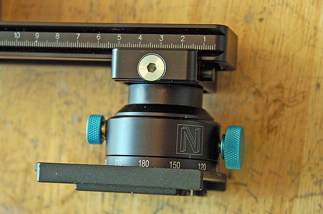
Here is the rail stop in position. |
|
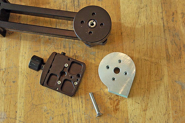
Using a lens ring mount clamped directly to the upper rotator positions the camera too close to the upper rotator. The Nadir patch shot does not work. I made a 3/4" riser block to put between the upper rotator and the clamp. I inserted a 1/4-20 3/8-16 adapter into the upper rotator. I could have used a 3/8" bolt, but that would require drilling out the clamp. I tried to modify the pano head as little as possible. Putting the adapter in the rotator allowed the use of a long 1/4-20 bolt. |
|
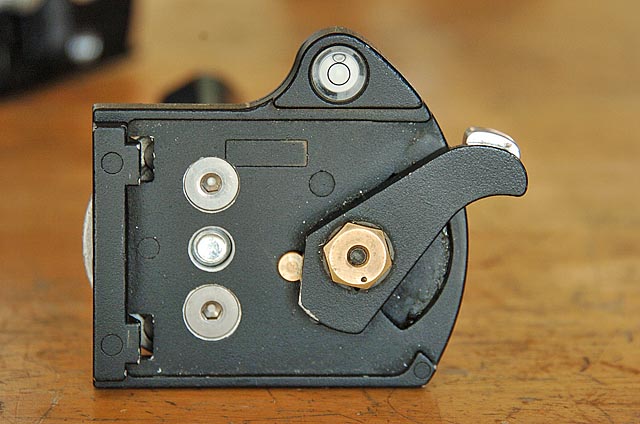
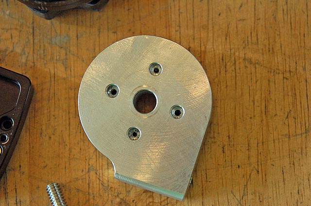
The side with the anti rotation bolt head holes. |
|
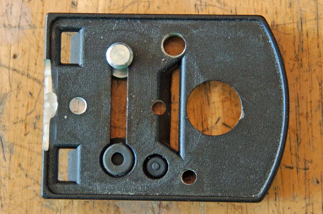
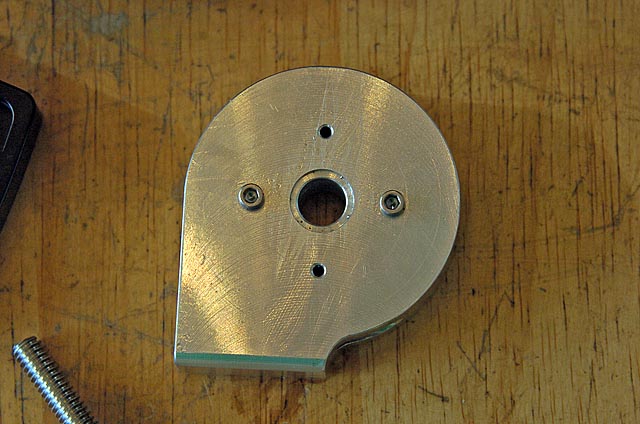
The side with the anti rotation bolts installed. The counter bore provides clearance for the 1/4-20 3/8-16 adapter that is installed on the rotator. |
|
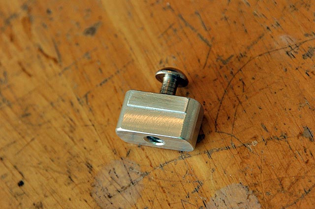
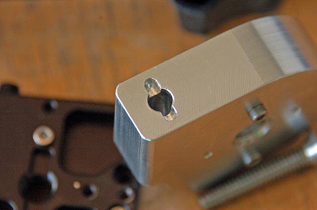
Here is a close up of the anti twist feature for mounting a remote control receiver to the pano head. I use a long 1/4" rod threaded on one end. A pin through the rod easily fits into the slot pictured above. Mounting a remote control directly to the hot shoe on the camera presents a problem when rotating the camera round. I like to stand outside the room when shooting a panorama. With the receiver mounted on the camera, there comes a time when the top of the camera is pointed away from me. I had to get into the room or try to bounce the IR signal in order to fire the camera. Putting the receiver in a "periscope" type position allows me to rotate the receiver around as I pivot the camera around. I can stay out of the room and easily fire the camera for every picture. |
|
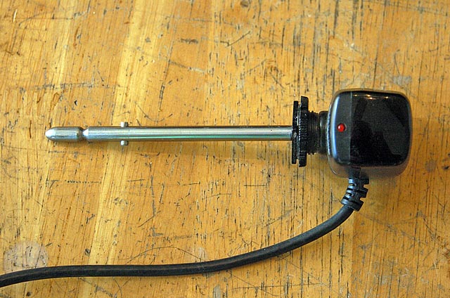
Here is what the receiver looks like mounted on the 1/4" rod. |
|
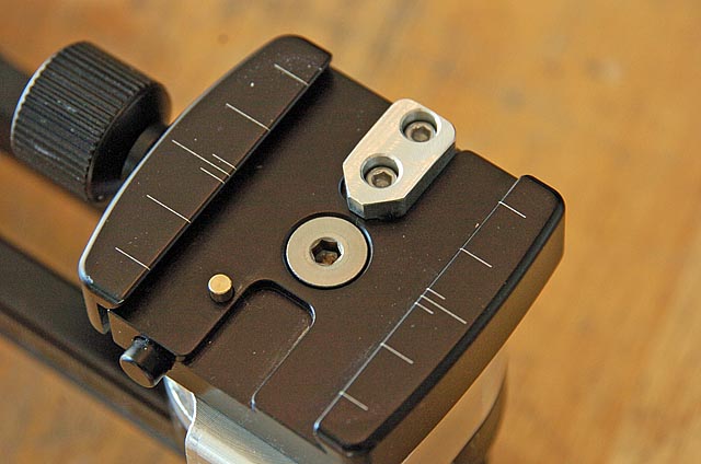
There is no rail stop for the lens ring clamp. On the back side of the rotator clamp there are two small tapped holes. I drilled and tapped them all the way through. I used the two existing holes for this upper clamp rail stop mount. |
|
And there you have it. None of these modifications are required. The M1L works great right out of the box. I do these modifications because I like to play and for my style of shooting, these modifications make it easier to shoot a pano. I limited modifications to drilling/tapping/counter sinking holes. No milling of the M1L directly was required. |